Search This Blog

Showing posts with label Energy. Show all posts

Thursday, October 5, 2023

Commercial Solar Rooftop Installation

Commercial solar rooftop installation is installing solar panels on the roof of a commercial building to generate electricity. Commercial solar systems are typically larger than residential ones, ranging in size from a few kilowatts to several megawatts.

The installation process typically begins with a site assessment to determine the suitability of the roof for solar panels. Factors such as roof orientation, shade, structural integrity, and available space are all considered. Once the site is deemed suitable, the solar installer will design and install a system that meets the specific needs of the building owner.

There are two main mounting systems for commercial solar panels: ballasted and attached. Ballasted systems use heavy weights, such as concrete blocks, to secure the panels to the roof. Attached systems use roof-penetrating hardware to attach the panels to the roof.

Once the mounting system is installed, the solar panels are attached. The panels are wired together in series and then connected to a solar inverter. The inverter converts the direct current (DC) electricity produced by the panels to alternating current (AC) electricity, which can power the building's electrical needs.

The final step in the installation process is to connect the solar system to the building's electrical grid. This allows the building owner to return excess electricity to the utility company.

Here is a more detailed overview of the commercial solar rooftop installation process:

  1. Site assessment: The solar installer will visit the site and assess the roof for suitability. This includes checking the roof orientation, shade, structural integrity, and available space.
  2. System design: The solar installer will design a system that meets the specific needs of the building owner. This includes considering the building's energy consumption, budget, and desired payback period.
  3. Mounting system installation: The solar installer will install the mounting system supporting the solar panels.
  4. Solar panel installation: The solar installer will attach the solar panels to the mounting system.
  5. Solar inverter installation: The solar installer will install the solar inverter, which converts the DC electricity produced by the panels to AC electricity.
  6. Grid interconnection: The solar installer will connect the solar system to the building's electrical grid.

Commercial solar rooftop installations can be completed in a few weeks, depending on the system's size and the installation's complexity.

Commercial solar rooftop installations offer several benefits to businesses, including:

  • Reduced energy costs: Solar panels can generate electricity for free, significantly reducing a business's energy costs.
  • Increased energy independence: Solar panels can help businesses become more independent and reduce their reliance on the utility grid.
  • Improved environmental performance: Solar energy is a clean and renewable energy source, which can help businesses reduce their environmental impact.
  • Increased property value: Commercial solar installations can increase the value of a business's property.

If you are a business owner considering a commercial solar rooftop installation, several resources are available to help you get started. You can contact local solar installers for quotes and consultations. You can also search for government and utility incentives that may be available to help offset the installation cost.

Tuesday, June 27, 2023

The general steps to compress syngas ,System and method for syngas clean-up

 Syngas, or synthesis gas, combines carbon monoxide (CO), hydrogen (H2), and other trace gases. The compression of syngas involves reducing its volume while increasing its pressure. Here are the general steps to compress syngas:

Understand the requirements: Determine the desired pressure level and the flow rate of syngas that needs to be compressed. This information will help you select the appropriate equipment.


Select a compressor: Choose a compressor that is suitable for handling syngas. Centrifugal compressors and reciprocating compressors are commonly used for gas compression. Consider factors such as the required pressure ratio, flow rate, gas properties, and efficiency when selecting a compressor.


Prepare the syngas: Syngas may contain impurities and contaminants that could damage the compressor or affect its performance. Pre-treat the syngas to remove particulates, moisture, sulfur compounds, or other impurities. This may involve using filtration, scrubbing, or drying equipment. Gasification of municipal solid waste (MSW) with subsequent utilization of syngas in gas engines/turbines and solid oxide fuel cells can substantially increase the power generation of waste-to-energy facilities and optimize the utilization of wastes as a sustainable energy resource. However, purification of syngas to remove multiple impurities such as particulates, tar, HCl, alkali chlorides and sulfur species is required. This study investigates the feasibility of high-temperature syngas purification from MSW gasification, focusing on catalytic tar reforming and desulfurization. Syngas produced from a downdraft fixed-bed gasifier is purified by a multi-stage system. The system comprises a fluidized-bed catalytic tar reformer, a filter for particulates and a fixed-bed reactor for dechlorination and desulfurization with overall downward cascading of the operating temperatures throughout the system. Novel nanostructured nickel catalysts supported on alumina and regenerable Ni-Zn desulfurization sorbent loaded on honeycomb are synthesized. Complementary sampling and analysis methods are applied to quantify the impurities and determine their distribution at different stages.


Compressor setup: Install the selected compressor in a suitable location, following the manufacturer's instructions and safety guidelines. Ensure the compressor is connected to the syngas source and any necessary pre-treatment equipment.


Compress the syngas: Start the compressor and adjust its settings to achieve the desired compression ratio. The compression process will reduce the volume of syngas while increasing its pressure. The specific procedures and controls will depend on the type of compressor used.


Cooling: Compressing syngas generates heat, which needs to be dissipated to avoid damage to the compressor and ensure efficient operation. Employ cooling mechanisms, such as intercoolers or heat exchangers, to remove excess heat during compression.


Storage and distribution: Once the syngas is compressed, it can be stored in suitable containers, such as high-pressure cylinders or tanks. If the compressed syngas needs to be transported, ensure proper safety measures and follow applicable regulations.


It's important to note that compressing syngas can be a complex process, and the specific requirements and equipment may vary depending on the scale and application. It is recommended to consult with experts or engineers experienced in gas compression to ensure safe and efficient syngas compression.

Wednesday, May 3, 2023

The steps to use paddy husk gasification for Rural Electrification

The energy cost now strongly depends on the prices of fossil fuels due to the world's intense fuel dependence on energy production. This is causing pain in most of the world's nations, and Sri Lanka is no different. From this perspective, the promotion of biomass as a source of renewable energy is significant to the country. Given that rice is the nation's leading food and the crop with the most considerable area under cultivation, it has been discovered that the rice husk (RH) produced during paddy processing has a significant potential for producing electricity.

Paddy husk gasification is a process that can be used to generate electricity from agricultural waste, specifically the husks of rice. The process involves heating the husks in a gasifier, which breaks down the biomass into a gas that can power an engine or a turbine to generate electricity.

The Husk Power Systems (HPS) and Decentralized Energy Systems India (DESI), two businesses that have successfully offered power access utilizing this resource, have popularized rice husk-based electricity generation and supply throughout South Asia. To examine the factors that make a small-scale rural power supply company profitable and determine whether a collection of villages can be electrified using a larger facility. Using a financial analysis of alternative supply alternatives that consider the residential and commercial electricity demands under various scenarios, Serving just consumers with low electricity usage results in the electricity-producing facility only being used to part of its capacity, which raises the cost of supply. Increased electricity use improves financial viability and considerably helps high-consumption clients. The feasibility and levelized cost of the collection are enhanced by integrating rice mill demand, especially during the off-peak period, with a predominant residential peak demand system. Finally, larger plants significantly reduce costs to provide a competitive supply. However, the more critical investment requirement, risks associated with the rice mill's monopoly supply of husk, organizational challenges related to managing a more extensive distribution area, and the possibility of plant failure could negatively impact investor interest.


Here are the steps to use paddy husk gasification for rural electrification:


Assess the availability of paddy husk: The first step is to determine the amount of paddy husk available in the rural area. This will help to determine the size of the gasification system that will be needed.

Choose the gasification system: There are different types of gasification systems available, including fixed beds, fluidized beds, and entrained flow gasifiers. The choice of the gasification system will depend on the amount of paddy husk available and the amount of electricity that needs to be generated. 

Install the gasification system: Once chosen, it must be installed in the rural area. The design should be located close to the source of the paddy husk to minimize transportation costs. 

Operate the gasification system: It must be operated properly to ensure electricity is generated efficiently. This involves feeding the paddy husk into the gasifier and maintaining the appropriate temperature and pressure.


Distribute the electricity: The generated electricity can be distributed to the surrounding rural area using a grid or a microgrid. The distribution system should be designed to meet the needs of the rural community. 

Monitor and maintain the system: It is essential to monitor the gasification system to ensure that it operates efficiently and to perform regular maintenance to prevent breakdowns and ensure a long lifespan.


In summary, paddy husk gasification can be a sustainable solution for rural electrification.

Thursday, March 30, 2023

What is Plant-e


Plant-e is a technology that generates electricity from living plants through a process known as microbial fuel cells (MFCs). MFCs use the natural metabolic processes of certain bacteria to break down organic matter, such as the sugars and other compounds produced by plants during photosynthesis, and generate electricity in the process.
Microbial Fuel Cells (MFCs) have been aptly described by Du et al. (2007) as “bioreactors that convert the energy in the chemical bonds of organic compounds into electrical energy through the catalytic activity of microorganisms under anaerobic conditions”.

In Plant-e's technology, electrodes are placed in the soil near the roots of the plants, and the bacteria living in the soil around the roots consume the organic matter and produce electrons, which can then be captured and used to generate electricity. The technology has potential applications in renewable energy, agriculture, and environmental monitoring.

While the technology is still in its early stages of development, it has shown promise as a sustainable and environmentally-friendly alternative to traditional forms of energy generation.

Thursday, March 16, 2023

Biorefineries

Biorefinery can be defined as a framework or a structure in which biomass is utilized optimally to produce multiple products and tries to be self-sustaining and not harmful to the environment.

 A biorefinery is a facility that integrates biomass conversion processes and equipment to produce fuels, power, and value-added chemicals from biomass. Biorefinery is analogous to today’s petroleum refinery, which has multiple fuels and products from petroleum. By producing several products, a biorefinery takes advantage of the various components in biomass and their intermediates, maximizing the value derived from the biomass feedstock.

Global issues such as environmental problems and food security are currently of concern to all of us. Circular economy is a promising approach towards resolving these global issues. The production of bioenergy and biomaterials can sustain the energy–environment nexus as well as substitute the devoid of petroleum as the production feedstock, thereby contributing to a cleaner and low-carbon environment. In addition, the assimilation of waste into bioprocesses for the production of valuable products and metabolites leads towards a sustainable circular bioeconomy. 

Thursday, April 9, 2020

PYROLYSIS TECHNOLOGY


Pyrolysis is the thermal decomposition of complex organic matter in the absence of oxygen to simpler molecules that can be used as feedstocks for many processes. The main products produced by the pyrolysis process are
  • activated carbon,
  • biodiesel and 
  • syngas.

Pyrolysis always consists of the endothermic reaction, though general combustion is done by the generation of heat reaction in the system
that produces solid, liquid, and gas, heating it at moderately high temperatures under a no oxygen or low oxygen atmosphere.
Biodiesel produced by the process of pyrolysis can be used purely as a fuel or for other petroleum products. The syngas is typically used for
combustion or to run turbines for power generation, including running the plant itself.
The biomass used in pyrolysis is typically composed of cellulose, hemicellulose, and lignin. The main parameters that govern the pyrolysis
process are 

  • temperature, 
  • heating rate, 
  • solid residence time, 
  • volatile residence time, 
  • particle size and 
  • density of particles.
Pyrolysis is, therefore categorised into three major types:
  • flash,
  • fast and 
  • slow pyrolysis 

and are respectively based on
  • temperature,
  • heating rate and 
  • residence time. 

The products of pyrolysis thus vary dramatically according to type. Cellulose is converted to
biochar and volatile compounds.

Wednesday, January 22, 2020

Carbon dioxide Removal from Biogas

A variety of processes are being used for removing CO2 from natural gas in petrochemical industries. Several basic mechanisms are involved to achieve selective separation of gas constituents. These may include physical or chemical absorption, adsorption on a solid surface, membrane separation, cryogenic separation and chemical conversion. 
Carbon dioxide is a noncombustible constituent of biogas lowers its heat value. Removal of carbon dioxide is not necessary when gas is to be used for cooking or lighting purposes only. A number of methods have been developed for CO2 removal (scrubbing) which depending upon the technique involved are called water-scrubbing, caustic-scrubbing, solid absorption, liquid absorption and pressure separation.
A brief description of these methods is as follows:

For biogas scrubbing physical/chemical absorption method is generally applied as they are effective even at low flow rates that the biogas plants are normally operating at. Also, the method is less complicated, requires fewer infrastructures and is cost-effective. 

Method # 1. Water Scrubbing:

One of the easiest and cheapest methods involves the use of pressurized water as an absorbent. The raw biogas is compressed and fed into a packed bed column from the bottom; pressurized water is sprayed from the top. The absorption process is, thus a counter-current one. This dissolves CO2 as well as H2S in water, which are collected at the bottom of the tower. 
In this method, gas is made to pass through water which absorbs part of CO2. The inherent limitation of this method is that it requires a large quantity of water. Based on studies carried out by H.M. Lapp, 7 ft(0.2 m3) of biogas at 68°F (20°C) and 1 atmospheric pressure (1.03 kg/cm2) requires 2.7 gallons (12.3 litres) of water for CO2 removal. CO2 is highly soluble in water. Spent water following absorption of CO2 becomes acidic and hence unsuitable for several applications as it corrodes metallic surface it comes in contact with.

Method # 2.CHEMICAL ABSORPTION

Caustic Scrubbing:

Chemical absorption involves the formation of reversible chemical bonds between the solute and the solvent. Regeneration of the solvent, therefore, involves breaking of these bonds and correspondingly, a relatively high energy input. Chemical solvents generally employ either aqueous solutions of amines, i.e. mono-, di- or tri-ethanolamine or an aqueous solution of alkaline salts, i.e. sodium, potassium and calcium hydroxides. Biswas et al. reported that by bubbling biogas through 10% an aqueous solution of mono-ethanolamine (mea), the co2 content of the biogas was reduced from 40 to 0.5-1.0% by volume. A solution can be completely regenerated by boiling for 5 min and thus can be used again
This method works on the principle that when caustic solutions are made to react with CO2 bearing gas streams, an irreversible carbonate-forming reaction followed by reversible bicarbonate forming reac­tion take place as per the following equations. This process involves the use of hydroxides of sodium, potassium and calcium.
In most industrial applications, no attempt is made to regenerate spent bicarbonate solution due to high steam requirement for this process. Carbon dioxide absorption into alkaline solution is adversely affected by slow conver­sion of dissolved CO2 molecules into more reactive ionic species. Mixing of liquid during absorption helps to achieve diffusion of gas molecules in the liquid and prolongs their contact time which adds to the former’s absorptivity.
Normality of caustic solution also affects the rate of absorptivity. With sodium hydroxide solution (NaOH), for instance, it was found that the rate of reaction is more rapid if normality lies between 2.5 to 3. Potassium hydroxide (KOH) is more commonly used in industrial scrubbing but it suffers from the limitation that it is not readily available in rural areas where biogas plants are normally located.
Calcium hydroxide [Ca(OH)2] on the other hand is generally preferred for biogas scrubbing as this chemical is more readily available and cost of operating a lime-water scrubber is also relatively less. The main limitation of lime-water scrubbing are difficulties faced in controlling solution strength, and removal of large amounts of precipitate from mixing tank and scrubber.

In most cases, sediment and suspended particulate matter need be removed in order to avoid clogging in pumps, high-pressure spray nozzles, packing and bubbling ap­paratus. Sodium hydroxide has the major advantage of being available in easily handled pellet forms that enable rapid and simple recharging of the scrubber. However, with NaOH solutions problems of suspended particulate matter are not totally eliminated.

 The absorption of CO2 in alkaline solution is assisted by agitation. The turbulence in the liquid aids to the diffusion of the molecule in the body of liquid and extends the contact time between the liquid and gas. Another factor governing the rate of absorption is the concentration of the solution. The rate of absorption is most rapid with NaOH at normalities of 2.5-3.0. 
CARBON DIOXIDE REMOVAL USING AMMONIA IN BIOGAS 
Ammonia is used as an absorbent in chemical scrubbing to remove CO2 from biogas. A continuous system consisting of the 1L digester was used for biogas production which was bubbled through an absorbent in 500mL gas washing bottle at a constant temperature in a water bath. The obtained biomethane potential was found to be 0.387 m3 CH4/ kg VS which simply means that more methane gas can be obtained when using ammonia for absorption. An increase in the gas flow rate leads to an increase in the mass transfer coefficient resulting in an increase in the rate of absorption. The initial CO2 concentration affects the removal efficiency because more work needs to be done for biogas with a high initial concentration of CO2. NH3 has better absorption capacity because higher biogas purity was achieved at lower NH3 concentration. The removal efficiency for NH3 increased from 69%-79% on average with CH4 concentration reaching over 85% vol. This is equivalent to a calorific value ranging from 25- 33.5 MJ/Nm3 which is promising in terms of the gas ability to run in an automobile engine. 

Method # 3. Method Developed by the IARI, New Delhi:

T.D. Biswas, et al., developed another method for CO2 scrubbing. It was found that biogas can be removed by bubbling it through 10 per cent aqueous solution of mono-ethanolamine (MEA). By single bubbling through a plain column of 6 cm height, carbon dioxide content in biogas was reduced to 0.5-1 per cent by volume from the initial value of 40 per cent.
Scrubbing column was made of an inexpensive plastic bubbler of 5 cm diameter and 15 cm height with only one orifice. The maximum removal of carbon dioxide was observed when bubbles moved out individually without colliding one another to form a continuous stream. Optimum gas flow rate to the regulator was estimated as 100 ml per minute which gave 60 ml of purified gas per minute in the reservoir.

The decrease in this rate of flow was not found to cause any further scrubbing. The initial pressure of the gas introduced into the bubbler was 10 cm of the water column and drop in pressure head was about 5 cm of the water column. Both caustic potash and monoethanolamine solution were effective in reducing the carbon dioxide content to 0.5 to 1 per cent.
Whereas spent caustic potash solution cannot be regenerated, MEA solution can be completely regenerated by boiling for five minutes and thus can be used again and again. Furthermore, MEA solution is far less caustic than other solutions used and therefore pose much fewer hazards for the skin. This method is thus very practical and economic for biogas scrubbing.

Method # 4. Pressure Separation:

This method works on the principle of compressing biogas beyond the limit of the critical partial pressure of impurities (CO2) with a temperature greater than the critical temperature of methane but below those of impurities. For instance, carbon dioxide liquefies when the gas temperature falls below 89.6 F (32 C) after compressing beyond 1106 psi (77.76 kg/cm).
Thanks, http://www.geographynotes.com/

Pressure Swing Adsorption (PSA) Systems for CO2 and Hydrogen Sulphide Scrubbing

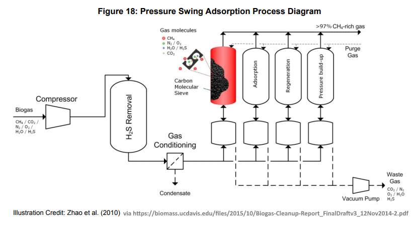
Pressure swing adsorption (PSA) systems, can be thought of as being molecular-sieves for carbon. PSA has been described are the second most commonly used biogas upgrading technology in Europe, after water scrubbing which is most likely the most popular. A typical system is composed of four vessels in series that are filled with adsorbent media which is capable of removing not only the CO2 but also water vapour, N2, and O2 from the biogas flow.
Typically in order to eliminate CO2 from biogas, the PSA upgrading takes place over 4 phases: pressure build-up, adsorption, depressurization and regeneration. The pressure build-up occurs by equilibrating pressure with a vessel that is at depressurization stage. Final pressure build-up occurs by injecting raw biogas. During adsorption, CO2, N2, and O2 are adsorbed by the media and the purified gas discharges as pure methane to a quality which will be far less corrosive and has a higher calorific value.

Recently developed gas-liquid membranes have been introduced, which operate at atmospheric pressures thereby reducing the energy consumption of compression. The use of specific solvent solutions allows the separation and recovery of the H2S and CO2.

Another approach to improving the economics of gas upgrading has been to recover the CO2 by cooling and recovering dry ice. This can then be sold as an industrial gas whilst the biogas is either used in its more concentrated form (80-90% CH4) or further refined to vehicle quality standard (>96% CH4).

Pressure Swing Adsorption

Pressure swing adsorption (PSA) is a method for the separation of carbon dioxide from methane by adsorption/desorption of carbon dioxide on zeolites or activated carbon at alternating pressure levels. This technology is often applied in the gas treatment industry as it also effectively removes volatile organic compounds, nitrogen and oxygen from industrial gas streams.Pressure swing adsorption process diagram

Sunday, March 17, 2019

'T Power H20,' the Eco-Friendly Bike

NAMED the 'T Power H20,' the eco-friendly bike was created by Ricardo Azevedo in Sao Paulo. The design features a combination of water and a single, external car battery used to produce electricity and separate the hydrogen from the water molecule. The process, involving a pipe-system, results in combustion which subsequently creates the energy necessary to power the bike.
The motorcycle does not need clean drinking water to run, and Azevedo demonstrated this when he went to the Tiete River, a river that is polluted, and filled the motorcycle up from that. He has been talking about the environmental benefits of his H20 motorcycle and of course the benefits of the cost associated with running a motorcycle that does not require fuel.
He said that one advantage of the motorcycle only using water to run was that it works with hydrogen that comes from the water and this means that the only thing that comes out of the exhaust pipe of the motorcycle is water vapour. He went on to point out that this is unlike a traditional motorcycle running on fuel which sends out carbon monoxide.

Friday, August 11, 2017

This Device Turns Salt Water Into Drinking Water Using Sunlight


The Eliodomestico is basically a personal desalination still, which operates similar to an “upside down coffee percolator.” The device is an open-source design, noted for its remarkable simplicity to build and use, as specifically intended by Diamanti when creating the solar still.
The device consists of two ceramic pieces that sit on top of one another. Within the top piece is a black container into which the salt water is deposited.
The sun heats the container of water, turning the water into steam. The pressure then builds until the steam is forced into a tube and is deposited into a container, where the water then cools, condenses and collects in the basin.
The Eliodomestico is designed to be carried upon the head when traveling, as is common place in developing countries where water is not a centralized commodity. People often are forced to walk great distances to collect this vital resource.

A revolutionary ceramic solar-powered still has the ability to combat one of the greatest threats to human life in the developing world, water insecurity. The solar still turns salt water into fresh water and can be built for under $50 U.S. dollars.
Water insecurity is one of the biggest issues facing the developing world today, but innovative designer Gabriele Diamanti has created a simple, yet effective, solution.


Method 2

A federally funded research effort to revolutionize water treatment has yielded an off-grid technology that uses energy from sunlight alone to turn salt water into fresh drinking water. The desalination system, which uses a combination of membrane distillation technology and light-harvesting nanophotonics, is the first major innovation from the Center for Nanotechnology Enabled Water Treatment (NEWT), a multi-institutional engineering research center based at Rice University.
NEWT's "nanophotonics-enabled solar membrane distillation" technology, or NESMD, combines tried-and-true water treatment methods with cutting-edge nanotechnology that converts sunlight to heat. The technology is described online this week in the Proceedings of the National Academy of Sciences.
More than 18,000 desalination plants operate in 150 countries, but NEWT's desalination technology is unlike any other used today.
"Direct solar desalination could be a game changer for some of the estimated 1 billion people who lack access to clean drinking water," said Rice scientist and water treatment expert Qilin Li, a corresponding author on the study. "This off-grid technology is capable of providing sufficient clean water for family use in a compact footprint, and it can be scaled up to provide water for larger communities."
The oldest method for making freshwater from salt water is distillation. Salt water is boiled, and the steam is captured and run through a condensing coil. Distillation has been used for centuries, but it requires complex infrastructure and is energy inefficient due to the amount of heat required to boil water and produce steam. More than half the cost of operating a water distillation plant is for energy.
An emerging technology for desalination is membrane distillation, where hot salt water is flowed across one side of a porous membrane and cold freshwater is flowed across the other. Water vapor is naturally drawn through the membrane from the hot to the cold side, and because the seawater need not be boiled, the energy requirements are less than they would be for traditional distillation. However, the energy costs are still significant because heat is continuously lost from the hot side of the membrane to the cold.
"Unlike traditional membrane distillation, NESMD benefits from increasing efficiency with scale," said Rice's Naomi Halas, a corresponding author on the paper and the leader of NEWT's nanophotonics research efforts. "It requires minimal pumping energy for optimal distillate conversion, and there are a number of ways we can further optimize the technology to make it more productive and efficient."
NEWT's new technology builds upon research in Halas' lab to create engineered nanoparticles that harvest as much as 80 percent of sunlight to generate steam. By adding low-cost, commercially available nanoparticles to a porous membrane, NEWT has essentially turned the membrane itself into a one-sided heating element that alone heats the water to drive membrane distillation.
"The integration of photothermal heating capabilities within a water purification membrane for direct, solar-driven desalination opens new opportunities in water purification," said Yale University 's Menachem "Meny" Elimelech, a co-author of the new study and NEWT's lead researcher for membrane processes.
In the PNAS study, researchers offered proof-of-concept results based on tests with an NESMD chamber about the size of three postage stamps and just a few millimeters thick. The distillation membrane in the chamber contained a specially designed top layer of carbon black nanoparticles infused into a porous polymer. The light-capturing nanoparticles heated the entire surface of the membrane when exposed to sunlight. A thin half-millimeter-thick layer of salt water flowed atop the carbon-black layer, and a cool freshwater stream flowed below.
Li, the leader of NEWT's advanced treatment test beds at Rice, said the water production rate increased greatly by concentrating the sunlight. "The intensity got up 17.5 kilowatts per meter squared when a lens was used to concentrate sunlight by 25 times, and the water production increased to about 6 liters per meter squared per hour."
Li said NEWT's research team has already made a much larger system that contains a panel that is about 70 centimeters by 25 centimeters. Ultimately, she said, NEWT hopes to produce a modular system where users could order as many panels as they needed based on their daily water demands.
"You could assemble these together, just as you would the panels in a solar farm," she said. "Depending on the water production rate you need, you could calculate how much membrane area you would need. For example, if you need 20 liters per hour, and the panels produce 6 liters per hour per square meter, you would order a little over 3 square meters of panels."
Established by the National Science Foundation in 2015, NEWT aims to develop compact, mobile, off-grid water-treatment systems that can provide clean water to millions of people who lack it and make U.S. energy production more sustainable and cost-effective. NEWT, which is expected to leverage more than $40 million in federal and industrial support over the next decade, is the first NSF Engineering Research Center (ERC) in Houston and only the third in Texas since NSF began the ERC program in 1985. NEWT focuses on applications for humanitarian emergency response, rural water systems and wastewater treatment and reuse at remote sites, including both onshore and offshore drilling platforms for oil and gas exploration.

Story Source:
Materials provided by Rice University.

Thanks  https://www.sciencedaily.com,http://thefreethoughtproject.com/